The infamous “battle of currents” 1888-89 between Thomas Edison on one side and Nicolaus Tesla and George Westinghouse on the other side, was about the future of the electric system. Which was the superior technology, Direct Current (DC) or Alternating Current (AC)? AC won, and for over half a century it looked like an outcome with the winner takes all.
1882 was the start of commercial public power. That year Thomas Edison’s companies built the Edison Electric Light Station in London and the Pearl Street Station in New York (September 4). The latter used reciprocating steam (generated from coal) engines, and initially serving 400 lamps at 82 customers. Two years later the engines had been replaced and the system expanded to 10,164 lamps at 508 customers. The current was DC, first at 110 Volt (V), but later upgraded to 220 V.
The Pearl Street Station became the prototype for central-station electric utility systems. In the next ten years several hundreds of similar systems were built in cities across the country. However, these DC systems had limitations. The DC generators had to be located within a mile of the load. The losses, caused by the resistance of the wires, could be reduced by increasing the voltage. The “only” problem was that there was no easy way to step up and step down the voltage.
On the contrary, thanks to the innovation of transformers, voltage could be stepped up and down in an AC system. This ability meant that transmission losses could be significantly reduced, enabling power generators to be located far away from the load. It was convincingly demonstrated in 1891, when a 30,000 V (30 kV) transmission line was built in Germany between Lauffen and Frankfurt, 175 kilometers (km). It was based on technology/patents developed by Mikhail Dolivo-Dobrovolsky.
It had been a tight race to be the first. Nicolaus Tesla had patents for a similar AC system with the key components of generators, transformers, and motors. George Westinghouse acquired Tesla’s key patents in 1888. They won a decisive win over DC, when the Chicago World’s Fair chose their AC proposal over Edison’s DC proposal. When the World’s Fair opened in May 1893 it 12 generators, each at 745 kW, providing power to 90,000 incandescent lights and 5,000 arc lights, as well as power to a railway, a moving walkway, and communications systems.
It was followed by another large win, the 32 km transmission line from the Niagara Falls to Buffalo in 1895/96. After that, it was with some minor exceptions all AC. Scaling generation, taking advantage of new steam turbine designs and remote hydro resources, it meant reduced costs for electricity. The progress was fast. In 1907 the first 110 kV system was built, and by 1920 the first 220 kV transmission. In 1950, Sweden pioneered 380 kV transmission, connecting hydro power in the north with load in the south. The first ultra-high voltage transmission was built by Hydro Quebec, 735 kV, in 1965, followed by 765 kV by AEP in the U.S. The first commercial AC transmission over 1,000 kV was energized 1982 in the Soviet Union at 1,200 kV.
For a while it looked that the future would be at even higher voltage levels. AEP and ASEA (ABB) had in 1976 demonstrated that 2,000 kV transmission was technically possible. This was at a time when the thermal power plants, nuclear and coal, was getting bigger and bigger, well over 1,000 MW (1 gigawatt) units, and large hydro projects around the world being considered for development. To transmit many gigawatts (GW) over long distances these ultra-high voltages were thought to be needed. However, it did not happen. DC was back in the game.
Like so many “disruptive changes” it had taken a long time to eventually happen. The first commercial HVDC (High Voltage DC) started operation in 1954 it was 96 km long cable between Sweden mainland and the Gotland island. The system was at ±100 kV and 20 MW. It had taken the development team at ASEA in Ludvika under Dr Uno Lamm’s leadership 25 years to achieve this milestone. It is an amazing history of engineering creativity and remarkable persistence, but also of strong and enduring support from the company, and the future first customer, Vattenfall (The Swedish State Power Board).
It was early recognized that HVDC could be a superior solution for long distance bulk power transmission, supplementing existing AC systems. The big challenge was to find a way to rectify the alternating current to direct current and then invert it back to alternating current. During the late 1920s and early 1930s serious attempts were made in England and Sweden using electrically controlled mechanical contacts. However, the focus internationally shifted to the concept of a mercury arc valve, which had been used in some industrial applications. The huge challenge was to scale the technology one hundred times or more. The breakthrough, originated from a patent application by Dr Lamm in 1928, was a concept of inserting grading electrodes between the anode and the cathode. However, it was not until 1933 the concept could be tested in experiments.
Less visible than the mercury arc valve development, but equally important for the HVDC technology was the development of HVDC system design concepts and related control philosophies, including building mathematical models. The DC system needed to be integrated with the AC system to work. It had not been done before and presented a whole new set of challenges. This was indeed pioneering work. It was led by Dr. Erich Uhlmann (system design) and Dr. Harry Forsell (control system design). Dr Uhlmann had come to Sweden in 1938, escaping Nazi-Germany. After his retirement Dr Uhlmann published “Power Transmission by Direct Current” (1975), which for decades became the “HVDC system design encyclopedia” for electric engineers.
Noticeable, Germany was also in the chase for HVDC. In fact, a consortium of AEG and Siemens had built a ±200 kV and 60 MW HVDC system with a 112 km connection with underground cables between Vockerede at the Elbe and Berlin, and ready to be energized April 4, 1945, but with the Russian army already at the Elbe it was too late. After the war Soviet Union disassembled the system and built it up between Moscow and Kashira, 112 km, and from 1950 used it for HVDC experiments and building know-how.
It was not a coincidence that the first commercial project was to an island. Cable connections longer than about 25-50 km with AC cables are not viable due to high losses. HVDC is superior. After the Gotland project other projects requiring HVDC submarine cables followed: Cross-Channel between England and France at ±100 kV and 160 MW in 1961, HVDC Inter Island 1 between the North and South Islands in New Zealand at ±220 kV and 600 MW in 1965 and Konti-Skan 1 between Sweden and Denmark at ±250 kV and 250 MW in 1965.
Picture by Eduardo Sanchez made available under Creative Commons 1.0 Universal Public Domain Dedication.
Next big technology step was use power semi-conductors, thyristors, for the converters instead of mercury arc valves. The concept of thyristors had been proposed already 1950 by William Shockley. It was developed by Bell Labs and GE. The first large scale commercial use was in color TVs in the early 1970s. It was early recognized that the thyristors could be scaled and arranged in series to provide the high voltages needed for HVDC applications. ASEA (ABB), who had acquired a license from GE, built a thyristor valve that was placed in the Gotland link 1967 for tests, which were successful and resulted in an order for expansion of the system, which was put in operation 1970. The first complete HVDC system with thyristors was Eel River, New Brunswick, Canada. It was a back-to-back (B2B) converter station rated 80 kV DC and 320 MW, built by GE, and energized in 1972.
The third big technology step came with the voltage source converters (VSC). Also, this time it was much about scaling a technology from industrial DC drives to utility scale. Using IGBTs (insulated-gate bipolar transistor) instead of thyristors provided an additional level of control. The thyristors could only be turned on. Thus, the thyristor-based inverters needed the connected AC system to turn off. The IGBTs could be turned on and turned off. It meant that the IGBT based inverters were “self-commutated”, could operate independently of the connected AC system. One of the many resulting advantages is that the control system automatically adjusts voltage, frequency, and flow of active and reactive power to the needs of the AC system. It can provide dynamic voltage support at any level of the active power.
ABB also pioneered this development with a pilot installation between Hällsjön and Grängesberg in Sweden 1995. For a second time in hundred years this was historic. It was here, in 1893, the first AC transmission system in Sweden was built, based on the patents developed by Jonas Wenström. The first commercial HVDC SVC project, rated at 50 MW ±80 kV, followed in 1999 at Gotland, connecting a windfarm on the southern part of Gotland to Visby. ABB called the technology HVDC Light, because of the much more leaner system design compared to traditional line commuted HVDC systems, from now on referred to “HVDC Classic”.
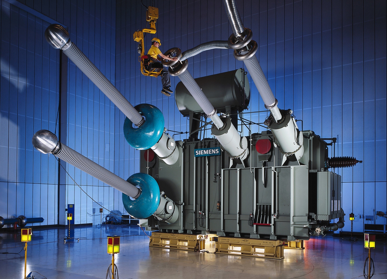
Creative Commons BY-NC-ND 2.0. Attribution: Siemens AG.
The Gotland project was followed one year later (2000) by a 36 MW back-to-back, Eagle Pass, connecting the asynchronous systems of Texas and Mexico. After that came (2003) the Cross Sound Cable, rated at ±150 kV and 330 MW, between Connecticut and Long Island. The scaling of HVDC Light, or now more commonly called HVDC VSC, has continued. The latest example, earlier this year (2021), is the 1,400 MW NordLink between Norway and Germany.
NordLink and many other HVDC projects with cables would not have happened without a remarkable development of the cables. This development has happened in parallel with the HVDC inverter development. It has happened less noticed but most significant since it continues to make more HVDC projects viable. Even though HVDC is superior to HVAC when it comes to cables over 50 kilometers distance, give or take, the costs of the cables could still be prohibitive for large power applications. Name of the game for the performance of a cable is the insulation. The 1954 Gotland link used a 7 mm oil-impregnated paper for the insulation. It performed well, but this type of insulation was difficult to scale for higher voltages/higher power. To provide adequate insulation at these higher voltage/power levels cables with pressurized oil as a key component of the insulation were developed. It still had limitations due size, complexity, and environmental concerns in case of damaged cables. The breakthrough came with extruded cross-linked polyethylene, XLPE, invented 1963 by GE Research Lab. Relatively fast XLPE reached commercial grade for 10-20 kV AC cables. However, to be useful for HVDC cables many challenges had to be overcome. It was not until 1999 the first HVDC XLPE cable was in operation, which was for the first HVDC VSC project at Gotland. After that, the progress has been fast. 1,000 MW is now possible with less than 8 mm of insulation. In comparison, the very first Gotland project was at 50 MW.
The combination HVDC VSC and XLPE cables are now triggering visions of “giga size” HVDC projects, for example Australia-Singapore Power Link, a 4,500 km 3 GW HVDC submarine cable(s), and Morocco – UK, 3,800 km 3.6 GW HVDC submarine cable(s). Whether these projects will happen or not, just the fact that they are proposed/planned demonstrates the huge potential of this combination of technologies. In both cases the intent is to bring large scale renewable energy developments to load.
While HVDC VSC with XLPE cables for subsea bulk power transmission is the only viable solution for distances longer 50 – 100 km, it can also be an alternative to overhead transmission lines, in urban space constrained areas and/or when NIMBY (“not in my backyard”) public opinion is blocking approvals. This has been the case in Germany. To bring wind power in the north to the load in the south, it was early recognized that new high-capacity transmission lines north-south would be needed as part of the Energiewende. The single most important project is the SuedLink, which has two HVDC lines running for the most part in parallel from Wilster and Brunsbüttel in Schleswig-Holstein to Grafenrheinfeld in Bavaria and Grossgartach in Baden Württenberg, respectively. After years of hard but unsuccessful work to overcome massive resistance against the overhead lines, the German government 2015 with new legislation paved the way for underground a cable alternative. It increased the estimate cost for the project from about $4 billion to about $13 billion but justified to get it built. Worth noticing is that the increase is “only” a little more than three times, it is substantially less than the old role of thumb that compared to overhead lines underground cables increased costs by a factor of 10.
For the efforts to decarbonize the electric power system, HVDC has become a key enabler. The applications are many: connecting asynchronous electric systems, remote renewable energy development (hydro, wind and solar), large scale offshore wind development, sub-transmission feeders into large cities.
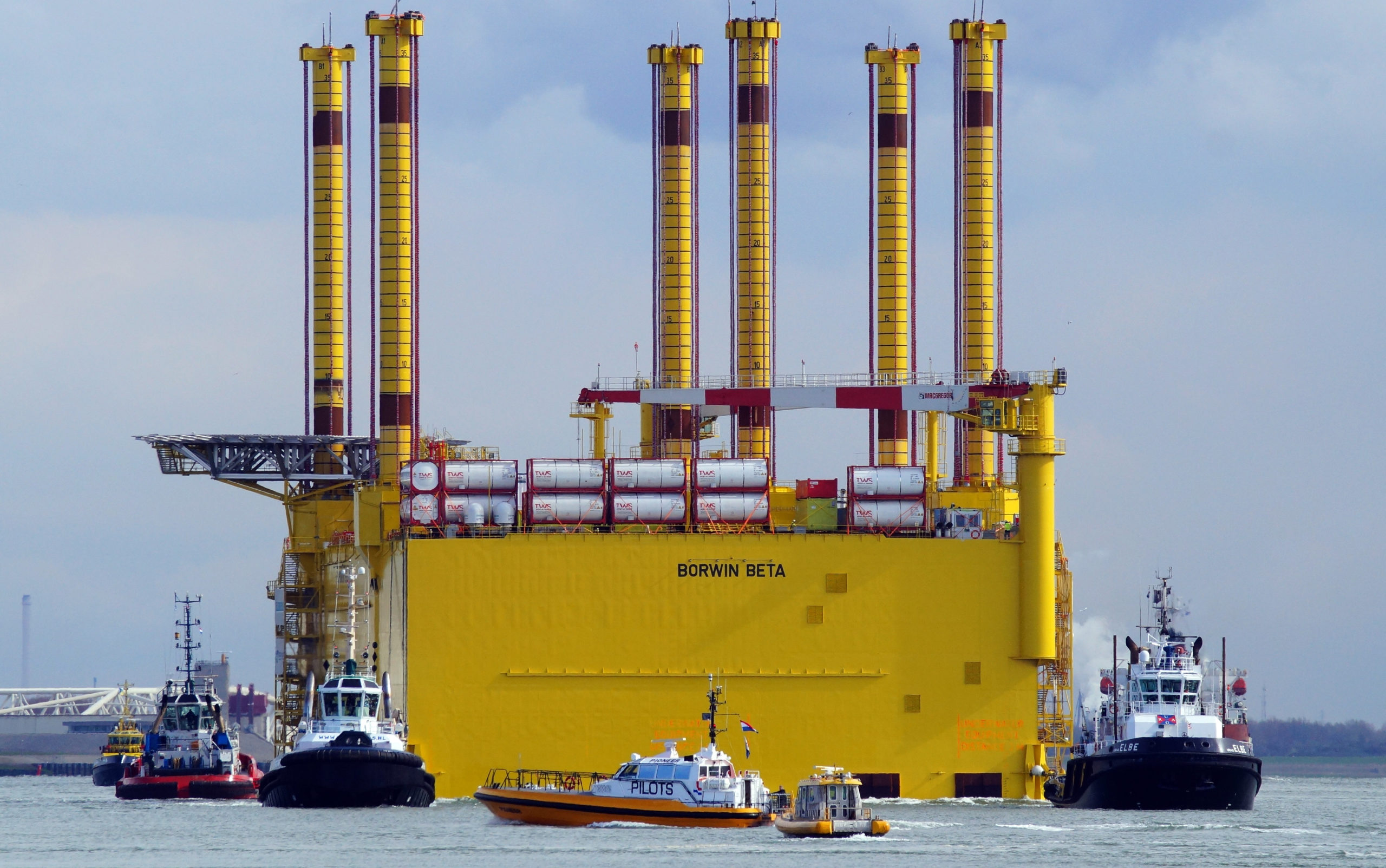
Creative Commons Attribution Share Alike 2.0 Generic License. Attribution: Kees Torn.
The three largest HVDC projects in the world are all bringing remote renewable generation to load. Jinping-Sunan, China, transmission at ±800 kV DC moves 7.2 GW of hydro power at a distance of 2,090 km. It has been in operation since 2012. One year later (2013) the Rio Madeira transmission in Brazil was commissioned. It is also remote, 2,385 km, hydro power. The system is at ±600 kV DC with a capacity of 7.1 GW. Xinjang-Anhui in China, in operation since 2019, is presently the largest HVDC system in the world. At ±1,100 kV DC it has the capacity of 12 GW. The purpose is to carry wind and solar energy 3,324 km to load in the greater Shanghai area.
Contrary to the battle of currents over a century ago, when a winner took all, supplementing the AC grids with HVDC has become the ultimate win-win. It will be a key characteristic of the Grid of the Future. The good news is that this future is now!
Footnote: ABB was created in 1988 as a merger of ASEA and BBC.
More read:
The Earliest Years of Three-Phase Power. 1891-1893. https://ieeexplore.ieee.org/ielx7/5/8944310/08944322.pdf?tp=&arnumber=8944322&isnumber=8944310&ref=aHR0cHM6Ly93d3cuZ29vZ2xlLmNvbS8=
The Early HVDC Development. https://library.e.abb.com/public/93e7f5ea0e800b7cc1257ac3003f4955/HVDC_50years.pdf
HVDC Proven Technology. (Siemens) https://www.brown.edu/Departments/Engineering/Courses/ENGN1931F/HVDC_Proven_TechnologySiemens.pdf